
GRE Tunnel
1. Network Topology
The network topology consists of two Xatellite devices. Xatellite1's eth1 interface is connected to Xatellite2's eth1 interface, serving as the basic working environment for implementing GRE tunnel functionality.

2. Objectives
Enable communication between terminal devices after configuring IPv4 addresses
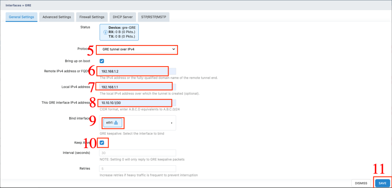
Enable communication between terminal devices after configuring GRE tunnels over IPv4, including:
- Remote tunnel endpoint IPv4 address configuration
- Local tunnel IPv4 address configuration
3. Equipment Requirements
| Device | Model | Version | Note |
|---|---|---|---|
| Xatellite | Xatellte | esix_x86-64_512MB_v1.6.0.R-fd99369c-24112922_STD | Xatellite1 |
| Xatellite | Xatellte | esix_x86-64_512MB_v1.6.0.R-fd99369c-24112922_STD | Xatellite2 |
4. Configuration Steps
- Initial Setup
- Connect the devices according to the topology diagram
- Configure basic network settings on both devices
- GRE Tunnel Configuration
4.1 Xatellite1 Configuration
- Configure interface IP address
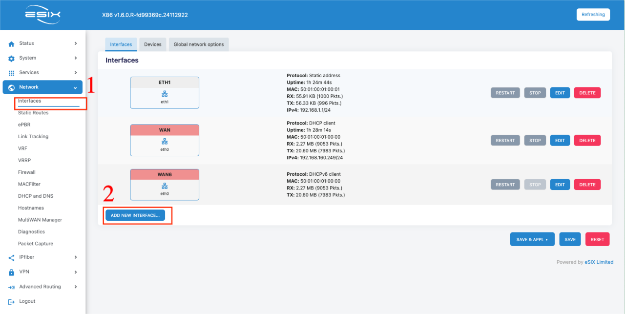

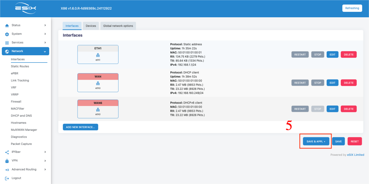
- Create GRE tunnel interface
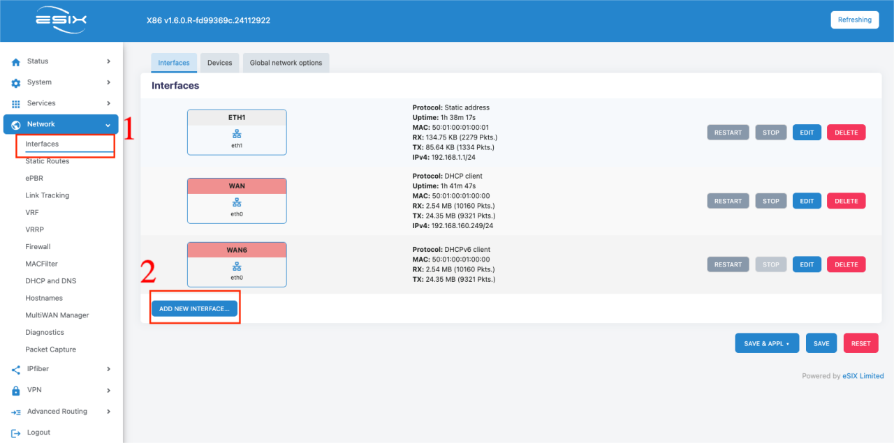
- Set up tunnel parameters

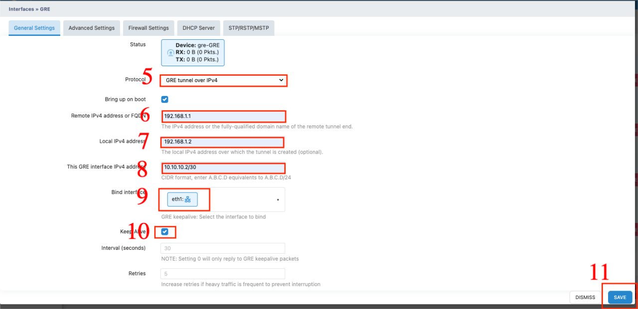
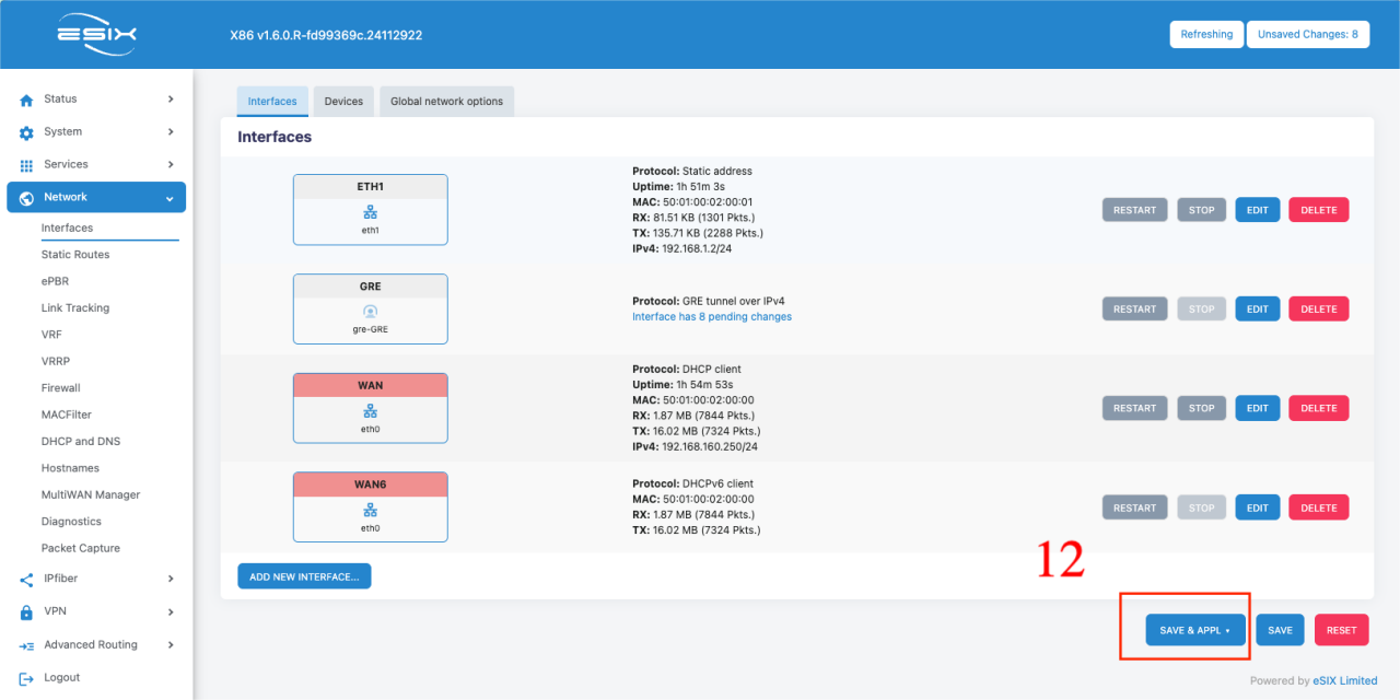
- Configure GRE tunnel interface
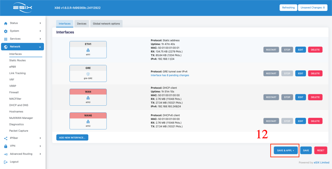
4.2 Xatellite2 Configuration
- Configure interface IP address
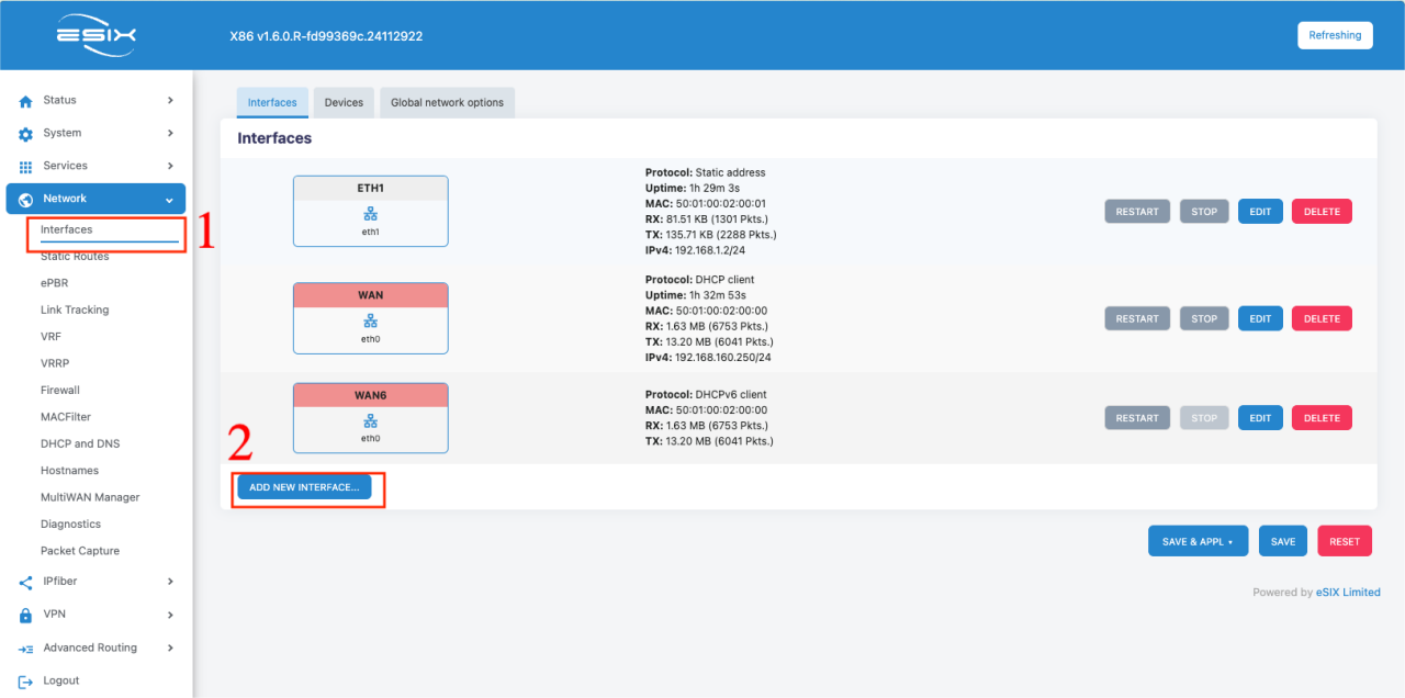

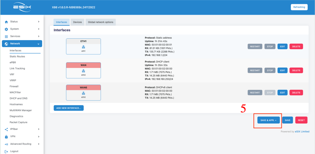
- Create GRE tunnel interface
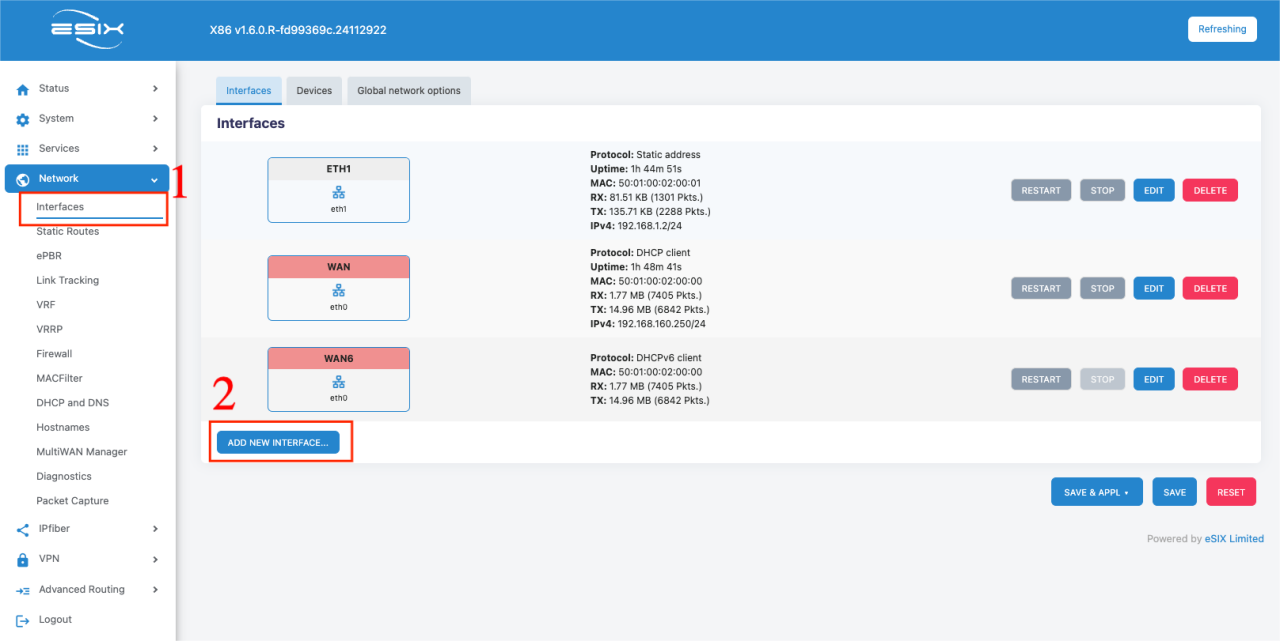
- Set up tunnel parameters

- Configure bridge interface
5. Testing and Verification
5.1 Basic Connectivity Test
Test IPv4 connectivity
- Ping test from Xatellite1 to Xatellite2
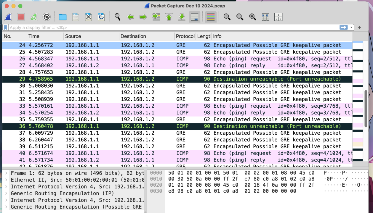
- Ping test from Xatellite2 to Xatellite1
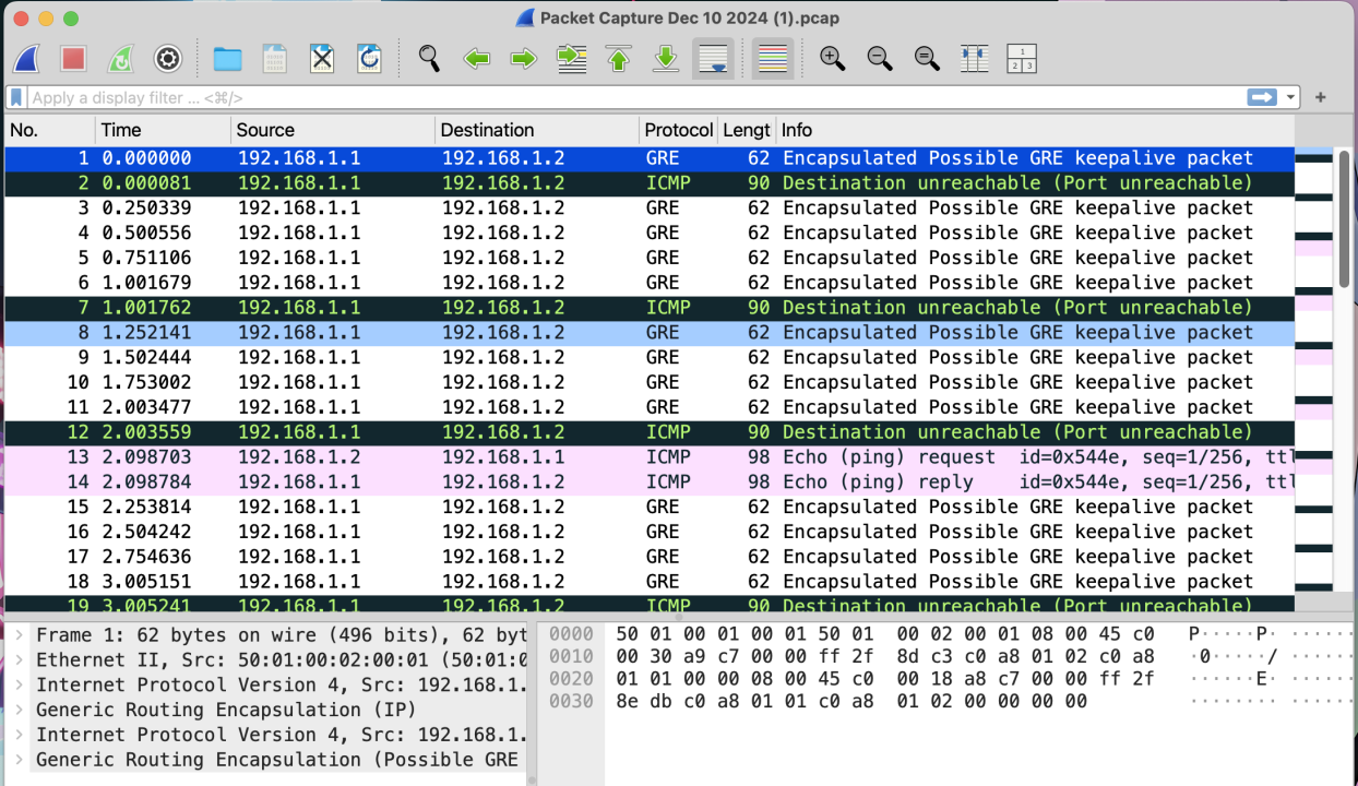
5.2 GRE Tunnel Test
Test GRE tunnel connectivity
- Ping test from Xatellite1 to Xatellite2 through tunnel
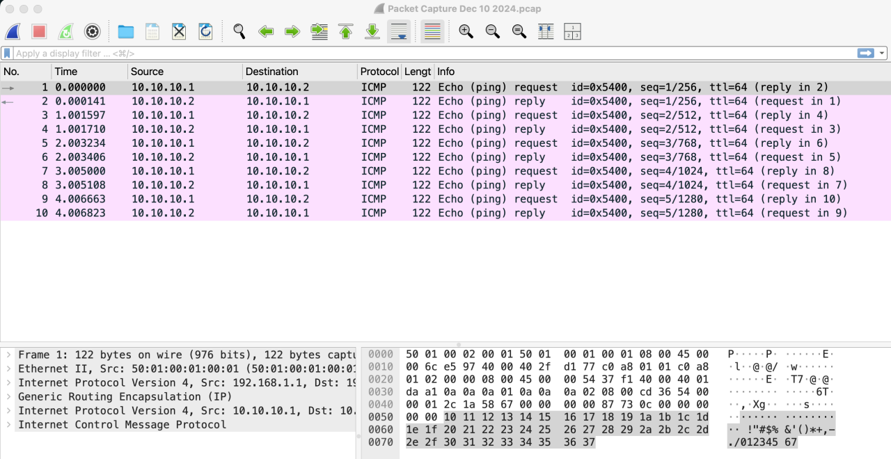
- Ping test from Xatellite2 to Xatellite1 through tunnel
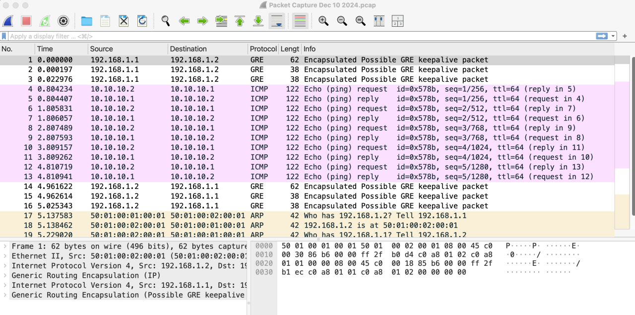
6. Conclusion
- IPv4 connectivity was successfully established between terminal devices
- GRE tunnel configuration was successfully implemented and verified
- All communication tests passed as expected