Xatellite+ Quick Start Guide
Packing Items
Connect the Hardware
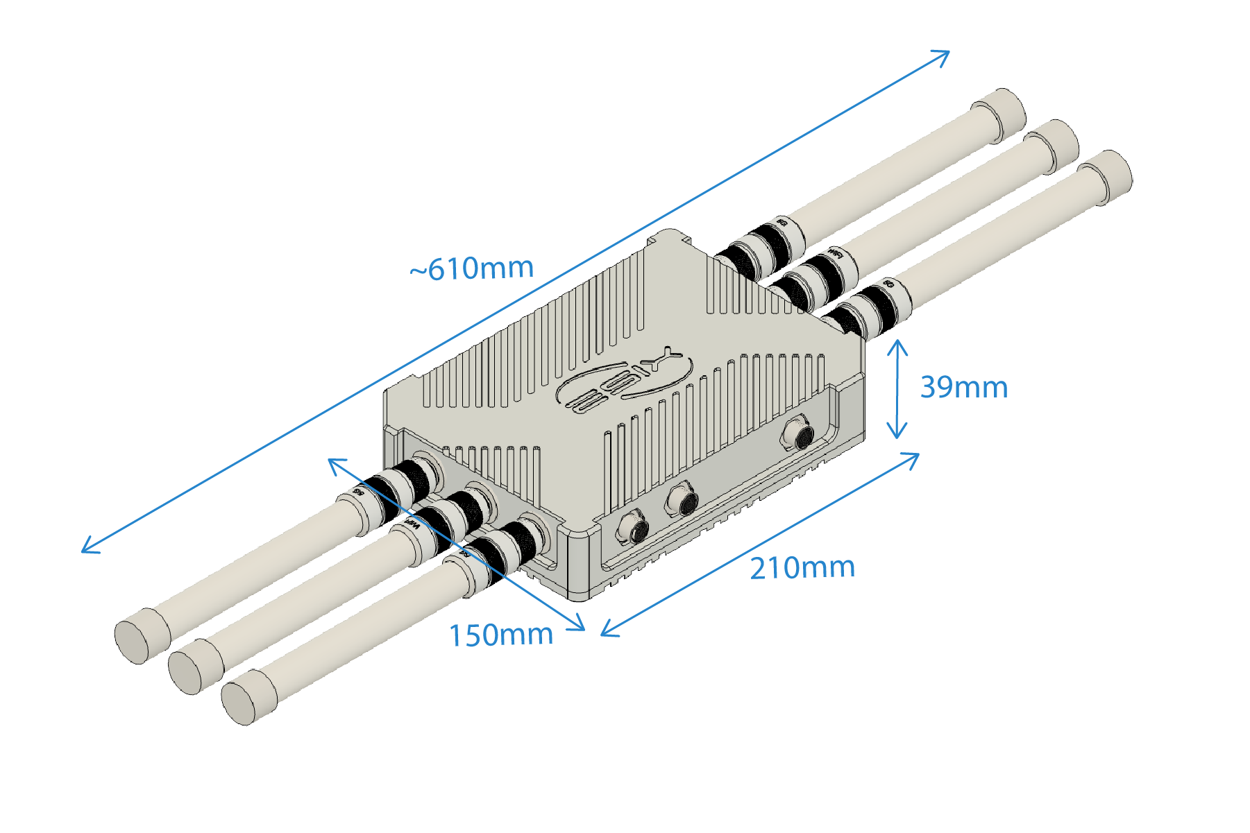
a. Install the antennas
⚠️ WARNING
The WiFi antenna and 5G antenna is label on it. Please make sure the WiFi/5G spot is connected with the relative antenna.
b. Insert the Nano SIM card
c. Connect power with poe
Verify the Hardware Connection
Hardware Description
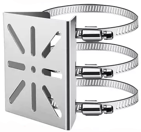
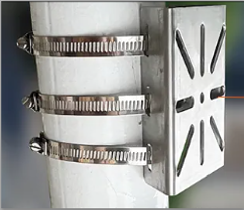
a. Xatellite+ install antenna dimension
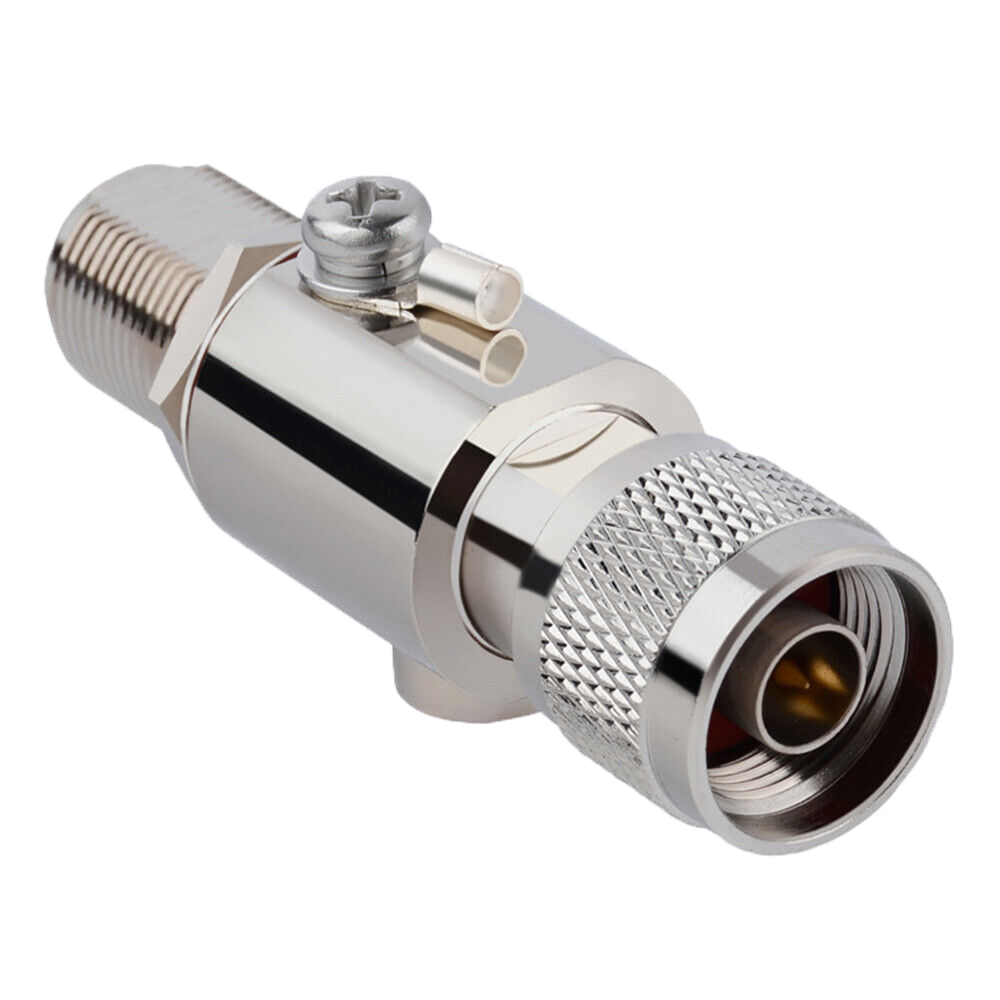
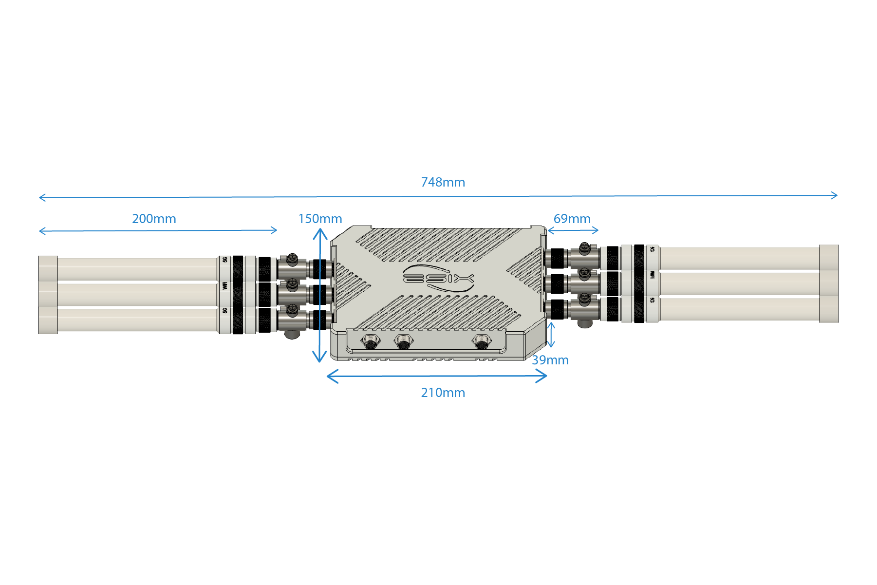
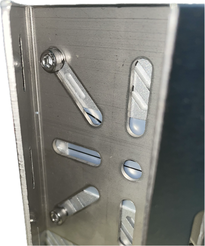
b. Xatellite+ install lightning dimension
📝 Tip
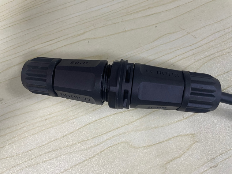
c. RJ45 waterproof connection
- Put the waterproof screw, waterproof rubber ring, and waterproof head into the cable in turn, and leave the crystal head exposed
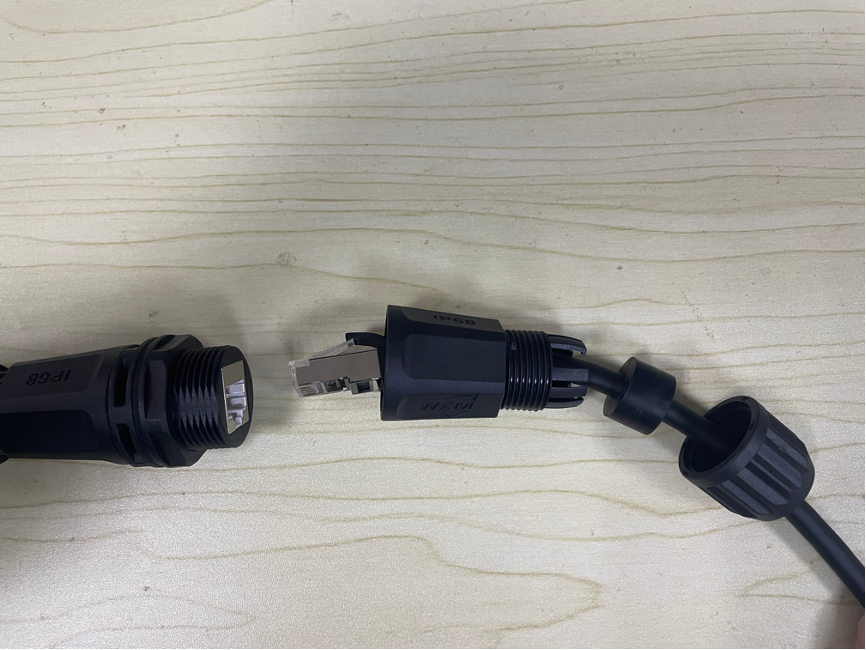
- Put the waterproof rubber ring into the fixed position of the waterproof head, and connect the connection head to the crystal head and tighten it
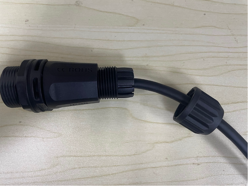
- Tighten the waterproof screw
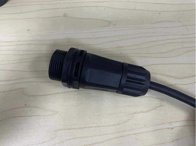
- The installation method of the other end is the same as the above
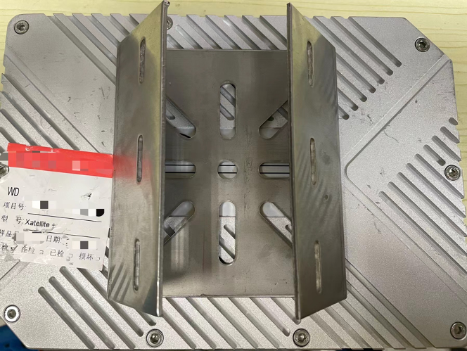
d. VESA hole distance
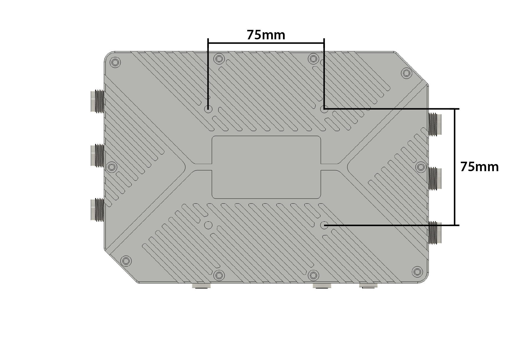
VESA standard bracket
VESA standard bracket types are numerous, among which the most common are the bracket
e. POE+ power supply
PoE power supply is a high-power PoE power supply device, equipped with a normal network input port and a PoE output port, and an AC power input port. The product is based on POE+ design, compatible with the cross-connection method of model and terminal; the device can integrate the normal network signal into the PoE signal output, with a maximum output power of 30W, supporting 10/ 100M/1000M networks, a transmission distance of up to 100m, and a maximum 6KV lightning protection, effectively improving the product's anti-interference ability; the product is widely used in PTZ high-speed balls, compact computers.
Product advantages:
Maximum output power of 30W;
90% conversion rate;
6KV lightning protection;
-10℃~55℃ wide temperature.
Enjoy the Internet
• Wired
Connect your computers to the router's LAN ports via Ethernet cables.
• Wireless
Find the SSIDs (network names) and wireless pass-word printed on the label at the bottom of the router.
Click the network icon of your computer or go to Wi-Fi settings of your smart device, and then select the SSID to join the network.
Customize the Xatellite+
Login
Make sure your computer is connected to the router (wired or wireless).
Launch a web browser and type in https://192.168.2.1.
- Username : admin
- Password : eSix6688
APN
Under the "Cellular > Configuration" page, this page support setting APN
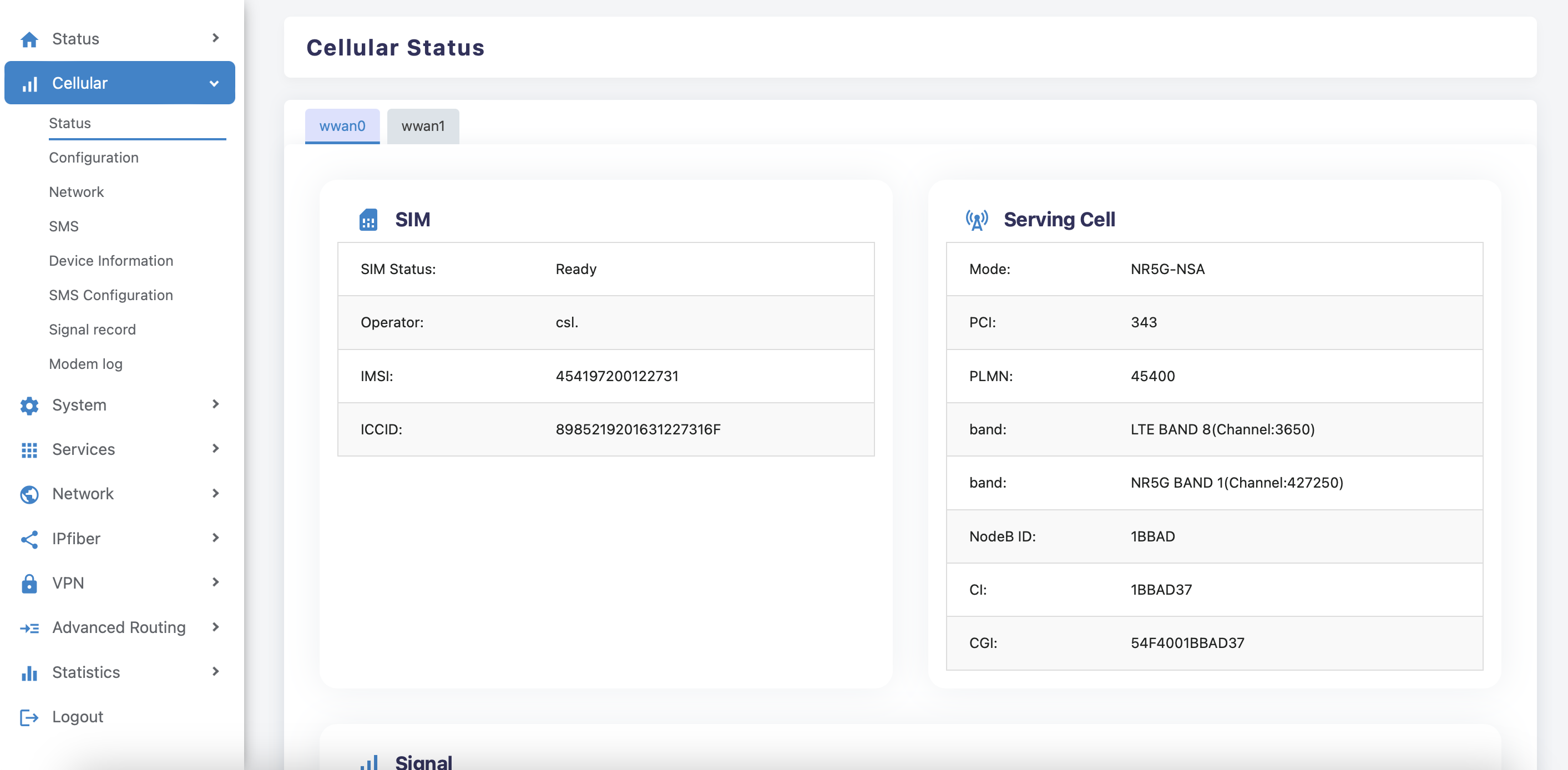
Successful dial
Under the "Cellular > Status" page, When cellular successfully dials up and obtains an IP address, it means that cpe can accessed the Internet normally.
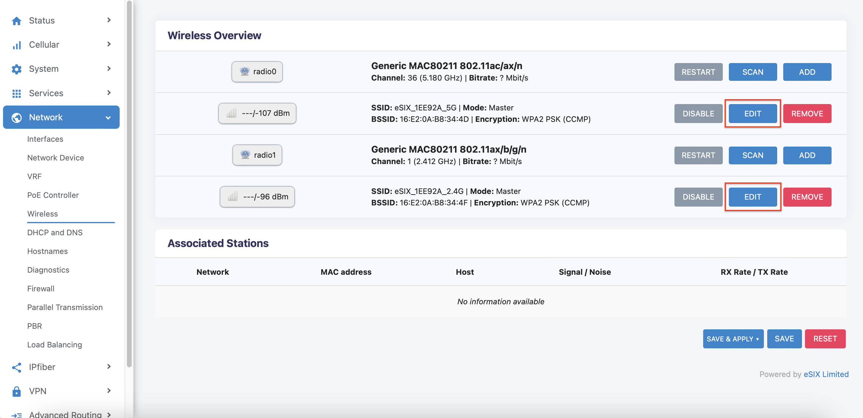
Change Wi-Fi password
Under the "Network > Wireless" page,this page can setting about Wi-Fi Configuration.
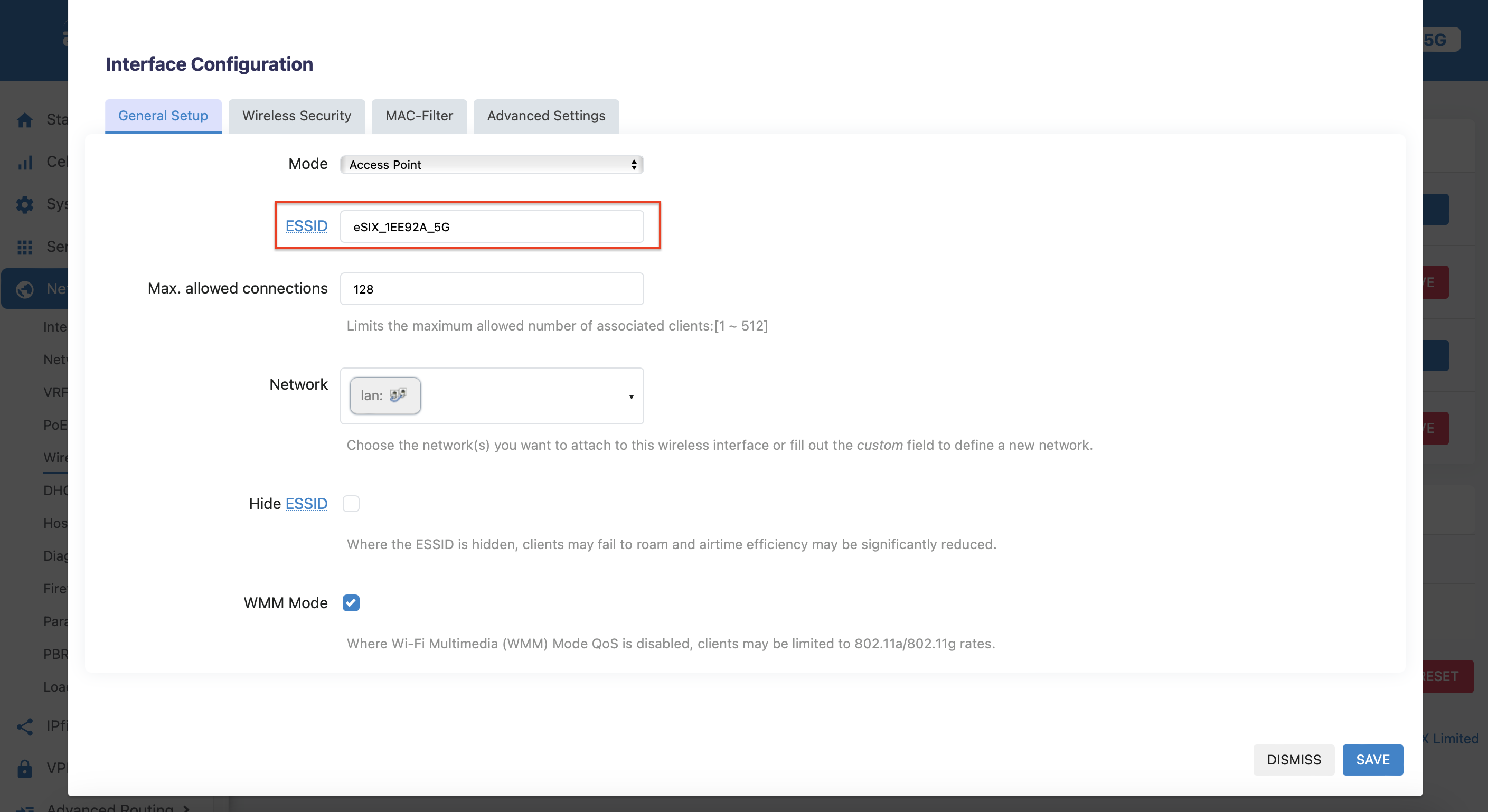
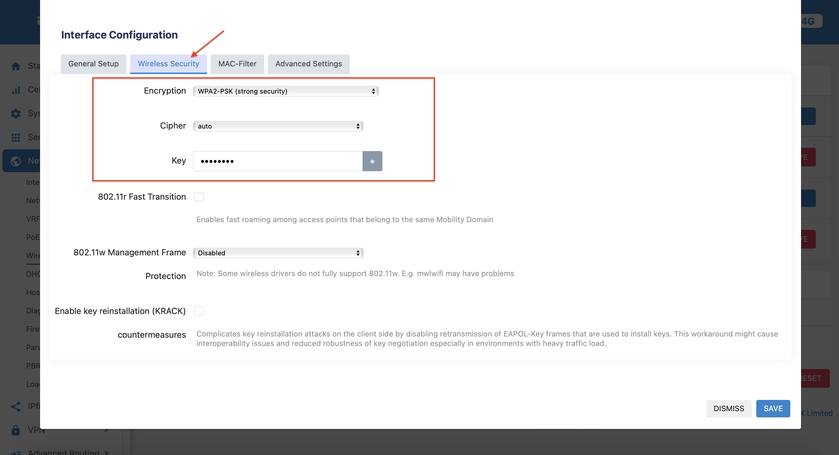
Click“Edit”,you can change the Wi-Fi SSID and password
Change ssid:
Change password:
Safety Instructions
- Keep the device away from water, fire, humidity or hot environments.
- Do not attempt to disassemble, repair, or modify the device.
- Do not use damaged charger or USB cable to charge the device.
- Do not use any other charger s than those recommended.
- Do not use the device where wireless devices are not allowed.
- Adapter shall be installed near the equipment and shall be easily accessible.