Application Note - IPFiber_L3
1. Introduction
The eSIX unique VPN tunneling technology can provide more efficient and reliable tunnels than legacy IPSec with up to 30% higher performance under the same eSIX hardware environment. The most beneficial is network and protocol agnostic and easy to build up.
Look into Figure 2, the devices are located at different networks and even regions. An end point could be created anywhere in the control center or deployed on cloud, the connected clients could be the TAP devices, VETH devices, and physical devices. Through wired or wireless networks like 4G/5G, the IPfiber tunnel is established as a virtual local LAN to bridge these devices in just milliseconds.
The tunnel is supported to build in Layer 3 and Layer 2, and is capable of package retransmission. For capacity and performance optimization, there could be multiple tunnels in Layer 3 for load balancing, in Layer 2 for local breakout, that are built for high availability redundancy as well as optimize the network resources. And all these professional setups could be done by the eSIX GUI by finger taps that IT free.
2. Configuration steps
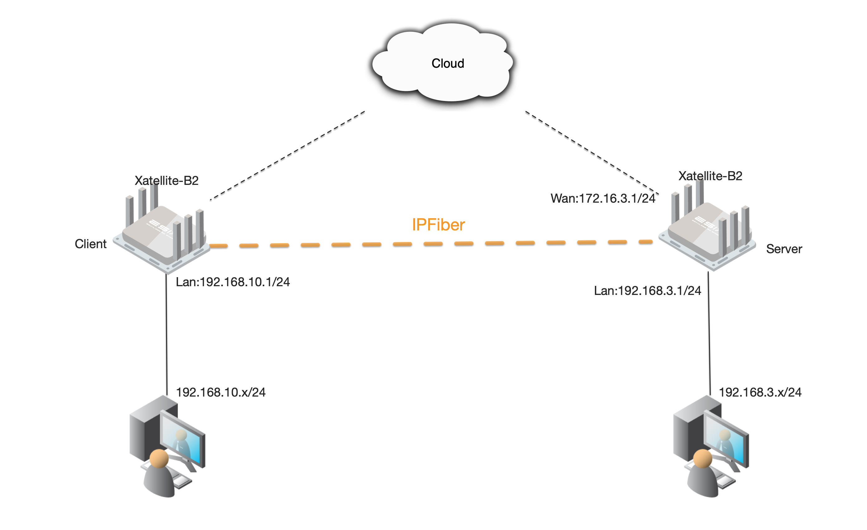
Example topology
preparation in advance
This topology requires that the Client needs to communicate directly with the WAN port or WWAN port (cellular network port) of the server
2.1 IPfiber single link
Layer3
Create a tunnel listening port
Server:
Go to 'IPfiber > Settings > Properties ' on the left menu bar

Click 'ADD' under the 'service port' page to enter the port ADD page, enter the port number and click save

Tunnel configuration
Server:
Create Tunnel user:
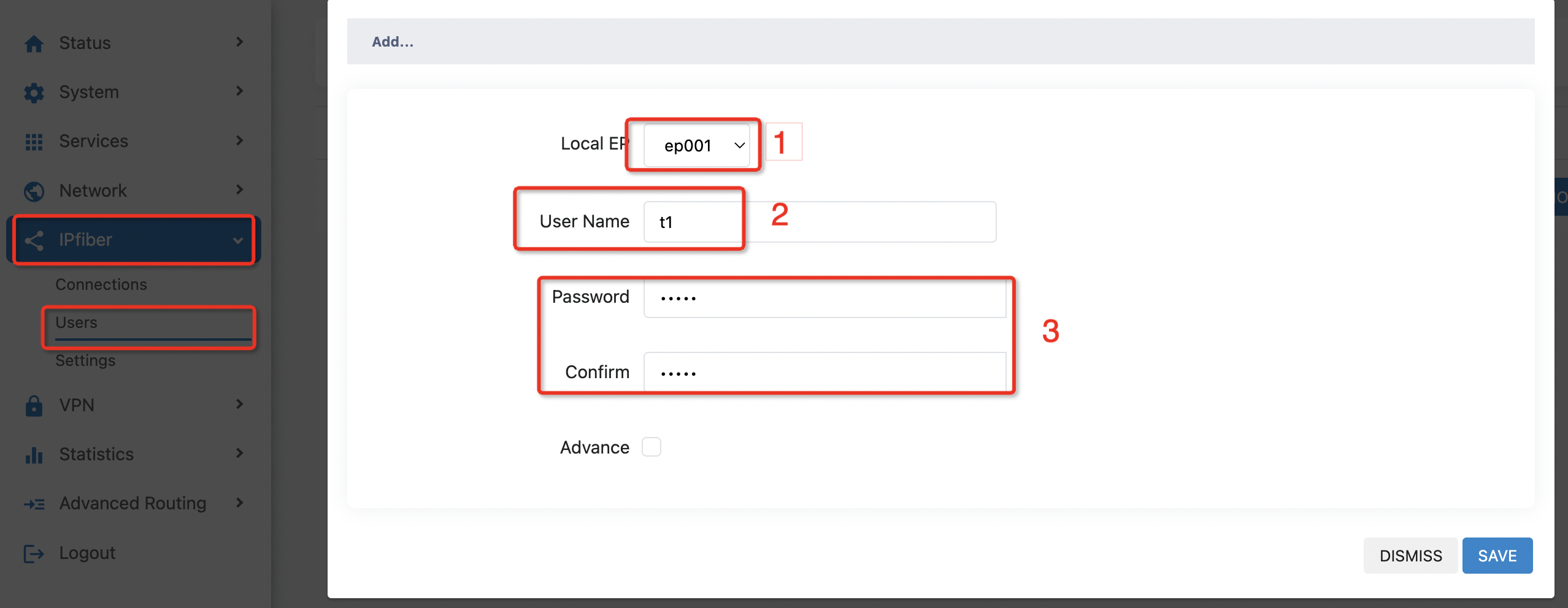
Go to 'IPfiber > user' click 'ADD' to go to the tunnel user creation page
Select the local terminal node at' 1' in the figure, where a tunnel corresponds to a terminal node
Fill in the user name at' 2' in the figure for tunnel setup
Set the password in' 3'
After the completion of the settings click on the lower right corner to save
Client:
Build a tunnel:
Try pinging the Wan Port Ip on the Server side first on the Client side. Once you have ensured that the IP is accessible, you can follow the following steps to build the tunnel
Go to 'IPfiber > connection' and click 'ADD' to go to the tunnel creation page
Fill in the tunnel name at' 4' in the figure
Select the local terminal node at' 5' in the figure
Fill in the WAN port address on the server side at' 6' in the figure
In Figure 7, enter the server listening port
Fill in the terminal node on the server side and the corresponding user name at' 8' and' 9' in the figure
In figure 10, enter the password for the server user name
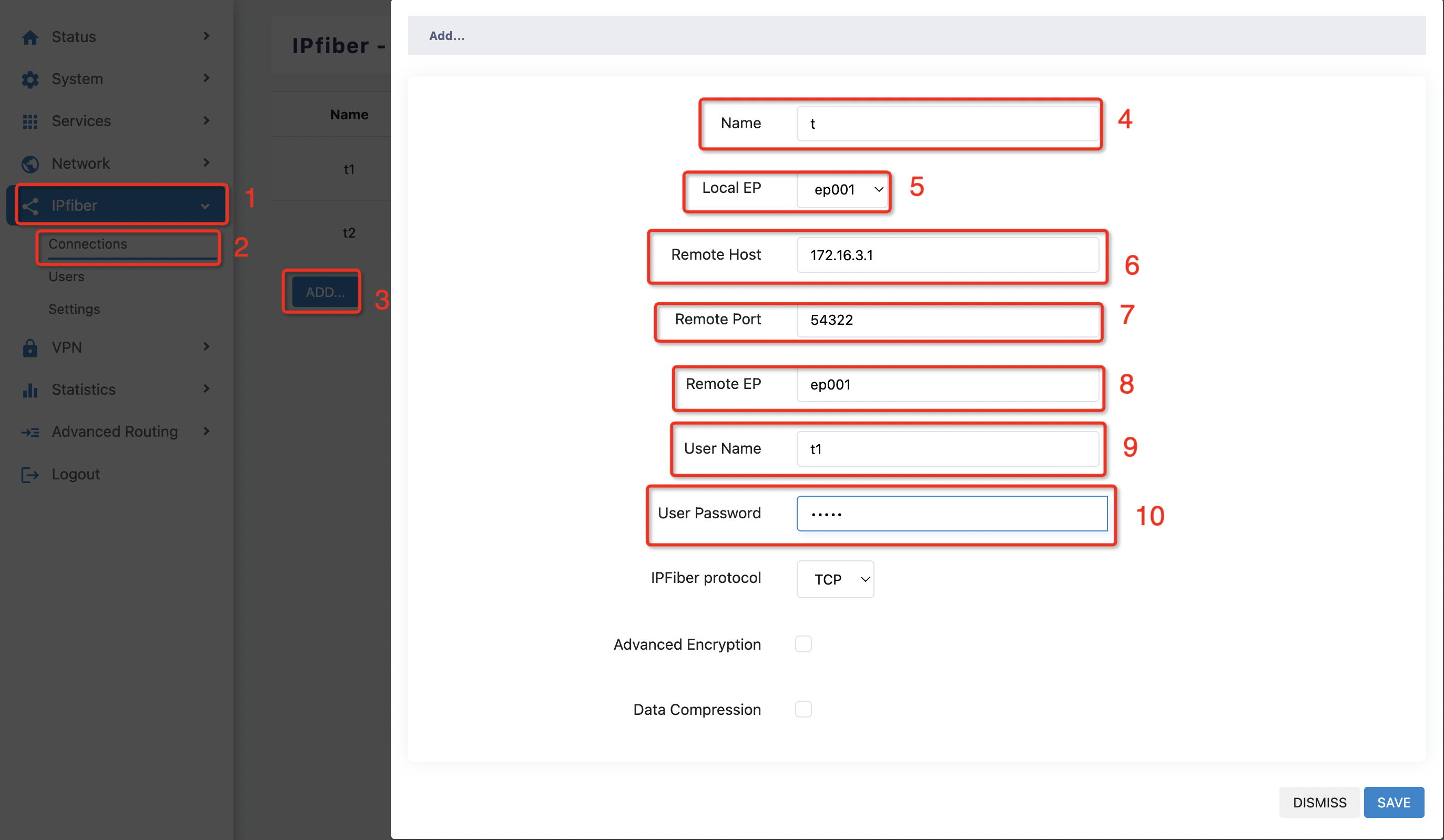
Once you have completed all of this, click save to see the tunnel already built, and the tunnel is in (open/online) state

If the server IP is accessible, the port is confirmed to be open, and the tunnel state is still not online, then go into 'network > Firewall' on the server side and Client side respectively to try to open the firewall wan zone inbound data

Server & Client:
On the 'IPfiber > Settings > interface binding' page, you can see that the system has preset 16 terminal nodes and their virtual interfaces
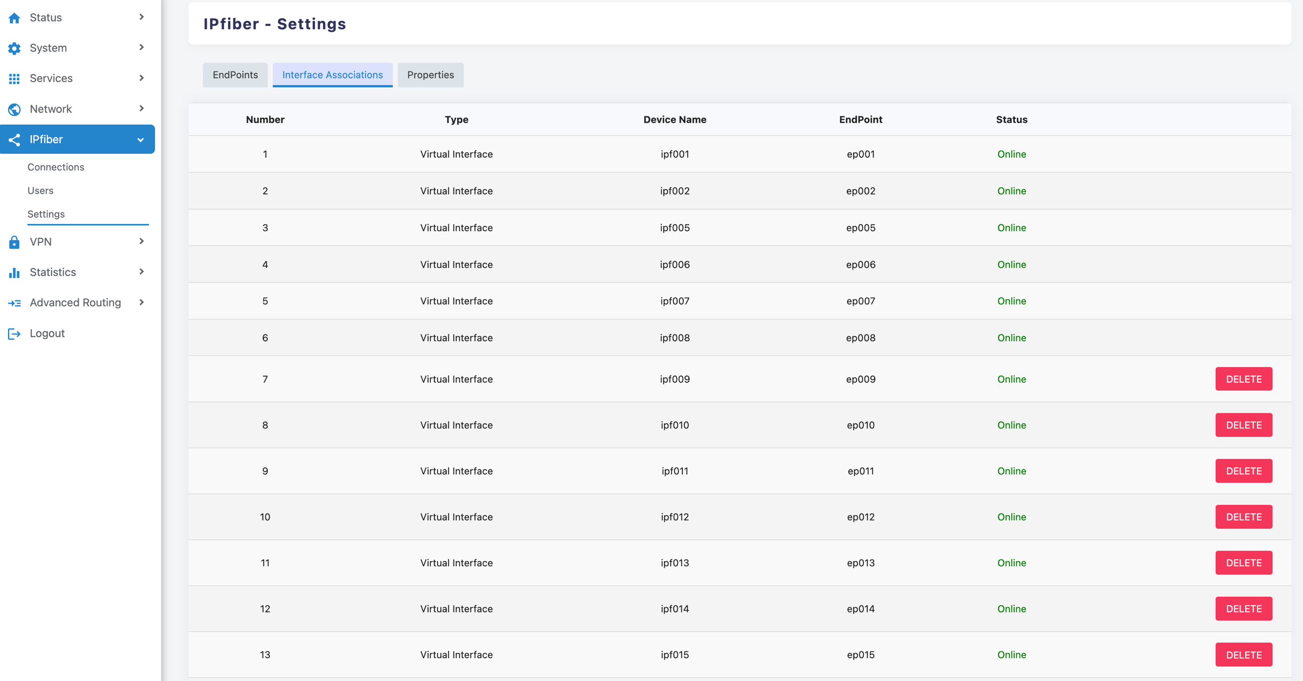
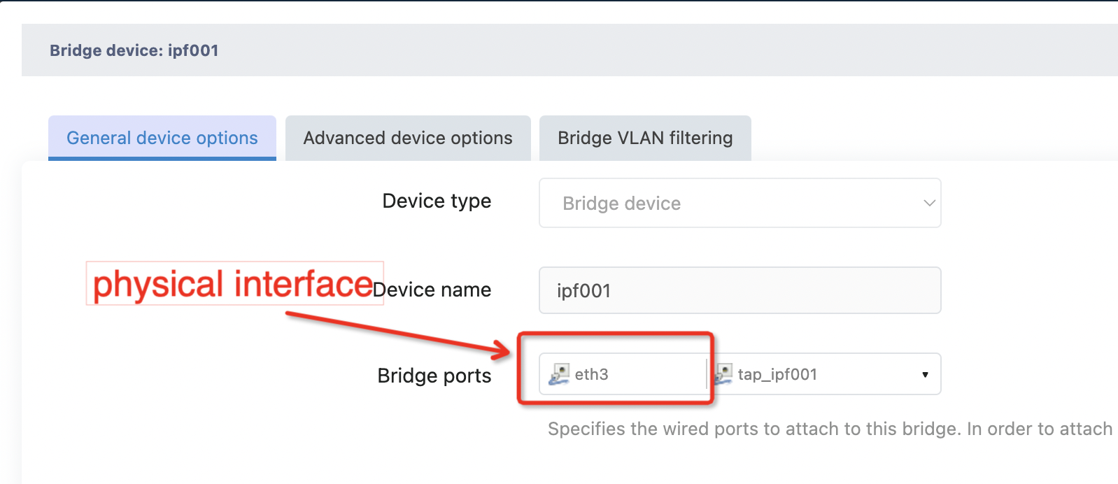
Note: The virtual interface for this page corresponds to a network device with the name“Tap” in the 'network > interface > devices' page, as shown below
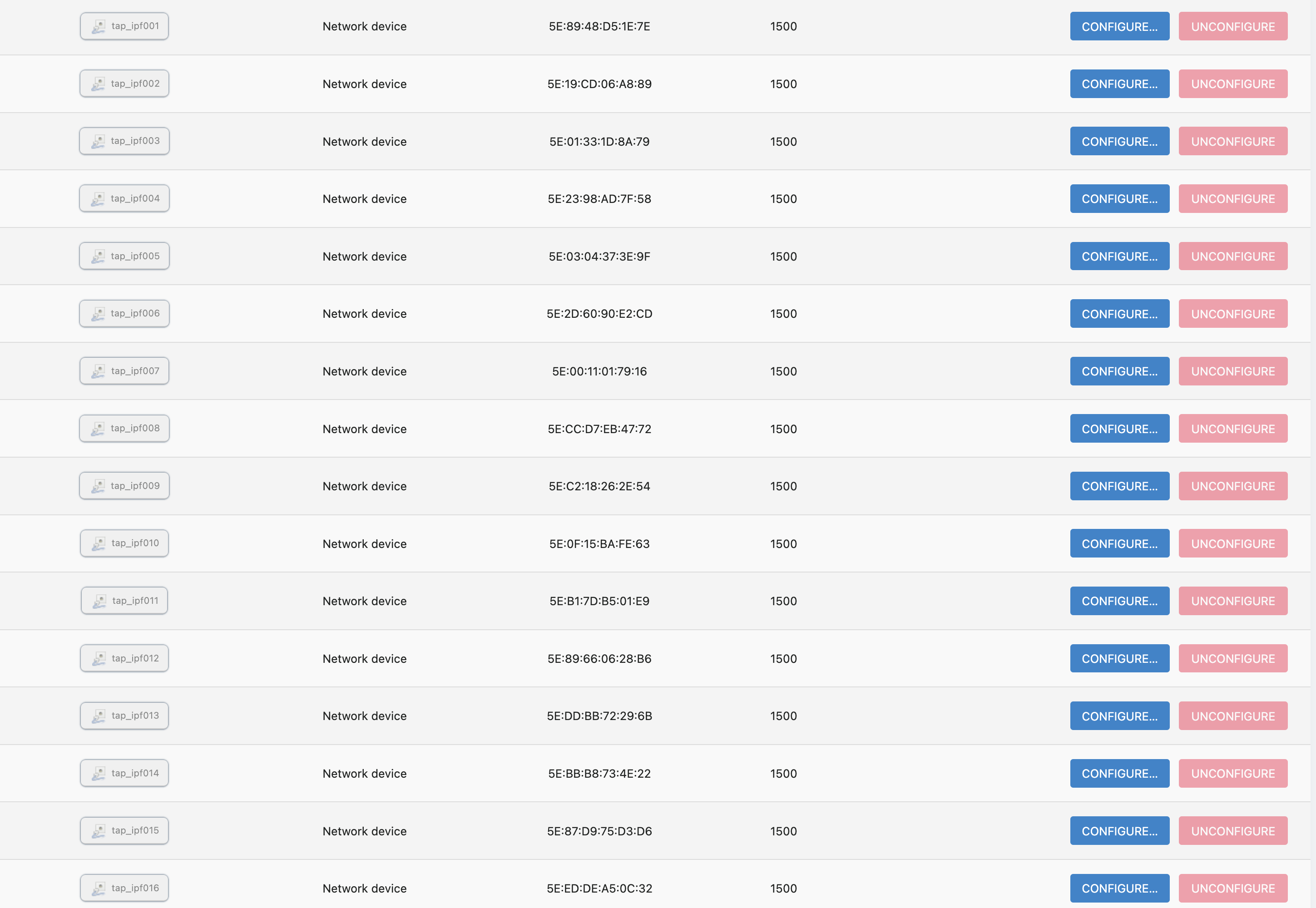
A bridge device named IPF00X is a virtual bridge containing a network device named TAP, not a virtual interface

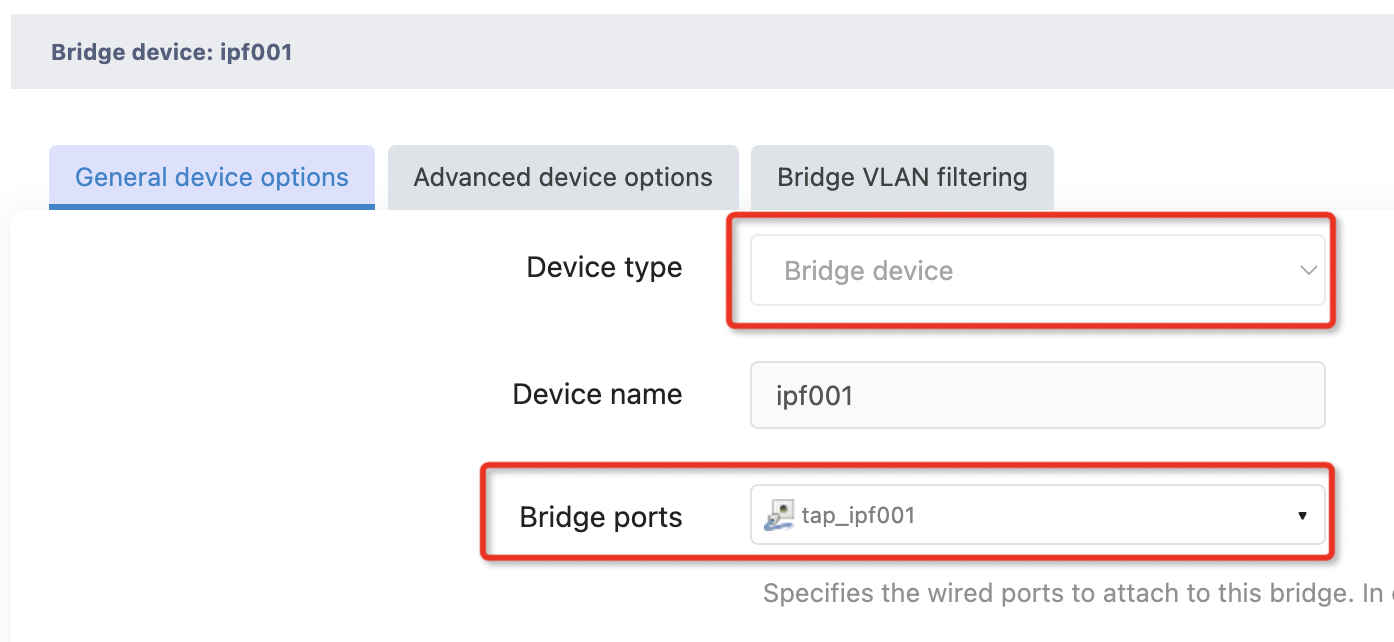
In the service configuration, the user only needs to put the physical interface which has the service traffic into the corresponding network bridge device, and then the service traffic can be introduced into the tunnel.
